Power Electronics Lab - Hands-On Experiments for Engineering Education
Power Electronics Lab - Hands-On Experiments for Engineering Education
| Country of Origin | India |
| MOQ | 1 Units |
| Price | USD 399 / Units |
| HS Code | 33517 |
| Category | Electronics & Electrical Electronic & Instrument Enclosures |
Contact Power Electronics Lab supplier for wholesale b2b price, customization or other inquiries
Post Buy Requirement
Get quick response from worldwide suppliers
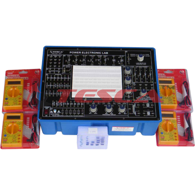
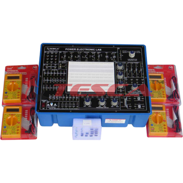
Power Electronics Lab
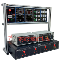
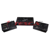
The Power Electronics Lab is used to perform power electronics circuit experiments. It is very useful in power electronics laboratories for performing power experiments in colleges and universities.
It is very for student to know about the characteristics of power electronics devices and the applications of power devices. The applications or power devices are in alarm circuit, lamp flasher, rectifiers, choppers, invertors. It is also used for commutation circuits.
The Equipment is Useful for Students at level in engineering / technical institutes (EC & Telecom) Technical training centers in communication organizations, R&D personal and practicing engineering in research labs and industry.
Technical Specifications:
- DC Power Supply on Board
- ± 5V at 100mA
- ± 12V at 150mA
- ± 15V at 50mA
- ± 35V at 50mA
- AC Power Supply on Board :
- 18V - 0V - 18V at 50mA
- 15V - 0V - 15V at 50mA
- Triggering Circuit on Board : 5 gate signal output
- Frequency range : 40Hz to 900Hz Variable
Amplitude :
- 12V
- PWM control of G1,G2,G3 and G4 Duty
- cycle control of “Gate” Signal is 0 to 100%
- Single Phase Rectifier : Firing angle control 0°-180° variables
- Firing Circuit on Board : Four gate signal output with isolation
- SCR Assembly : 4 SCRs 2P4M, 600V,2A
- Power Devices : IGBT-G4BC20S, MOSFET-IRF540, UJT-2N2646, DIAC-DB3, TRIAC-BT136, PUT-2N6027
- Circuit Components On Board :
- Capacitor 0.01uF, 0.047uF , 0.1uF, 0.33uF, 1uF/63V(4Nos.) 2.2uF/50V
- Diode 1N4007 (8Nos.)
- Zener Diode 9V (1Nos. )
- Inductors 10mH, (1Nos.), 68mH (2Nos.)
- Load Resistance 120E, 270E, 1K, 2K2, each 5W
- Resistance on Board (½ W) 22E/5W, 100E/2W, 220E/2W
- Resistance on Board(1/4W) 10K (3Nos.), 22K,33K,47K,
- Potentio Meter 4K7(2Mos.), 1M(1Nos.)
- Pulse Transformer on Board : 2 Nos. PT4502, 1:1 and one is PT4503 1:1:1
- Toggle Switch : SPST (1Nos.)
- Power Requirements : 220V ±10%, 50Hz
Experiments On Board Using Breadboard:
- To study the characteristics of SCR and plot its V-I Characteristics.
- To study the Gate control characteristics of SCR and It's graph.
- To study the characteristics of UGT and calculate interbase resistance and intrinsic standoff ratio.
- To study the characteristics of MOSFET.
- To study the characteristics of IGBT.
- To study the characteristics of DIAC and plot its V-I Characteristics curve.
- To study the V-I characteristics of TRIAC.
- To study the characteristics of PUT.
- To study of class B commutation circuit.
- To study of class C commutation circuit.
- To study of class D commutation circuit.
- To study of class F commutation circuit.
- To study the Resistor Triggering circuit.
- To study the Resistor-Capacitor Triggering Circuit (Half wave).
- To study the Resistor-Capacitor Triggering Circuit (Full wave).
- To study the triggering of SCR using UJT.
- To study the Triggering of SCR using 555 IC.
- To study the Triggering of SCR using Op-Amp 74I IC.
- To study of the ramp and pedestal triggering using anti-parallel SCR in AC load.
- To study of the UJT relaxation oscillator.
- To study of the voltage commutated chopper.
- To study of the Bedford inverter.
- To study of the single phase PWM inverter using MOSFET.
- To study of the single phase PWM inverter using IGBT.
- To study the half-wave controlled rectifier with resistive load
- To study the half wave controlled rectifier with RL load.
- To study the full-wave controlled rectifier (mid-point configuration) with resistive load.
- To study the full-wave controlled rectifier (mid point configuration) with RL load.
- To study the fully controlled bridge rectifier with resistive load.
- To study the fully controlled bridge rectifier with RL load
Product Usages
The Power Electronics Lab is a pivotal tool for conducting hands-on experiments in power electronics circuits. It is extensively used in educational institutions such as colleges, universities, technical institutes, and training centers to facilitate practical learning experiences for engineering students.
With its comprehensive set of experiments and user-friendly design, this lab equipment enables users to explore the characteristics and applications of various power electronics devices.
Whether studying alarm circuits, rectifiers, choppers, or inverters, this lab provides an effective platform for users to gain practical insights into power electronics principles and applications, enhancing their understanding and proficiency in the field.
Product Keywords: Power Electronics Lab, Power Electronics Lab supplier, Power Electronics Lab manufacturer, Power Electronics Lab India, Power Electronics Lab wholesale, Power Electronics Lab price.
Product Images
Supplier Info
| Company Name | : | |
| Business Type | : |
|
| Supplier Phone: | : | +9198291xxxxx |
Supplier Info:
Tesca Technologies Pvt. Ltd.
 Rajasthan, India
Year Established: 2009
Business Type:
- Manufacturer
- Trading
Contact Supplier About This Product
Contact Supplier for product pricing, customization or other inquiries
Send Your Message to: Tesca Technologies Pvt. Ltd.
More Products From This Supplier
Related Products
- Fan FT35-II/FT35-III Fiberglass Reinforced Plastic Axial Fan
- Moisture Balance
- Communication Equipment 4G/5G Shell
- Omron E2E-X2F1 proximity switch brand new
- RTM1511 High-precision Resistance Thermometer 0.1°C Accuracy
- Cleanroom ESD Swab
- Scpc026 Pogo Pin Probe
- Varistor Resistance Chip Resistor
- Ultrasonic flow meter for waste water and river
- Manual start/stop button
- DOG-1902 Industrial Dissolved Oxygen Meter
- Triple Wide Enclosed Cabinet - 8937
